


-
Local EU Warehouses

-
14-Day Price Guarantee

-
Hassle-Free Warranty

-
Lifetime Customer Support


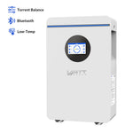
WattCycle 48V 100Ah nástěnná solární baterie s aktivním vyvážením & Bluetooth
Prime Day Sale Ends In:
The integrated 3A active balancing system continuously optimises each cell, improving overall efficiency and extending lifespan.
A 100A intelligent BMS provides comprehensive protection, ensuring safe operation under varying loads and environmental conditions. The optimised internal structure and thermal design enhance heat dissipation and long-term stability.
With 6000+ cycles, smart monitoring, and full inverter compatibility, this battery delivers a dependable and future-ready solution for your solar energy system, designed to perform reliably for years to come.
✔ Higher-performance EV Grade A Cells
✔ L398 x W200 x H625 mm, 45kg
✔ 3A active balance provides faster multi-channel equalization efficiency, reduces energy loss, and maximizes battery life
✔ Touchable LCD screen to help you monitor and check the battery in real-time
✔ Triple communication mode: CAN/RS232/RS485 monitoring
✔ 100A BMS, 100A Max. Cont. Dis-/Charge Current
✔ LED light dtrip capacity display
✔ Dual terminal design for high current
✔ Real-time monitoring via WattCycle App
✔ Support 20P to achieve Max. 102,4 kWh energy
-
Local EU Warehouses
-
14-Day Price Guarantee
-
Hassle-Free Warranty
-
Lifetime Customer Support


Tech Specifications
| Model | 48V 100Ah Wall-mounted Solar Battery | 48V 314Ah LiFePO4 Solar Battery |
|---|---|---|
| Battery Mode | LiFePO4 Battery | |
| Battery Capacity | 5.12kWh | 16.07kWh |
| Internal Resistance | ≤ 13.9mΩ | ≤ 13.9mΩ |
| Single Cell Capacity | 100Ah | 314Ah |
| Rated Operating Voltage | 51.2V | 51.2V |
| Standard Input Current | 50A (Max.100A) | 150A (Max.305A) |
| Standard Output Current | 50A (Max.100A) | 150A (Max.305A) |
| Overcharge Protection | 58.4V | |
| Overcharge Protection Recovery | 53.6V | |
| Overdischarge Protection | 40V | |
| Overdischarge Protection Recovery | 47.2V | |
| Charging Overcurrent Protection | 110±10A/10s | 310±10A/10s |
| Discharging Overcurrent Protection | 120±10A/10s | 310±10A/10s |
| Internal Resistance Recovery Methods | a. Remove the Charger, b. Remove Loads | |
| Power Delivery | 60% | |
| Equalization | 3A Active Balance | |
| Parallel Capability | Up to 20 units | |
| Power Failure Self-Consumption | ≤300uA | |
| Communication Protocol | RS485, CAN, RS232 | |
| Recommend Charging Temperature | 0°C to 55°C | |
| Recommend Discharging Temperature | -20°C to 60°C | |
| Dimensions (L×W×H) | 398 x 200 x 625 mm | 450 x 240 x 880 mm |
| Weight | 45kg | 122kg |
Compatible Inverters
| Inverter Brands | Communication Ports |
|---|---|
| Afore | CAN |
| Aiswei | CAN |
| Aohai | RS485 |
| Deye | CAN |
| GOODWE | CAN |
| GROWATT | RS485/CAN |
| GT | RS485 |
| Hoymiles | CAN |
| INVT | CAN |
| LUXPOWER | CAN |
| MEGAREVO | CAN |
| MUST | CAN |
| MUST | RS485 |
| NEXT | 232 |
| PYLON TECH | RS485/CAN |
| SAJ | CAN |
| SAKO | RS485 |
| Sacolar | RS485 |
| Senergy | CAN |
| SMA | CAN |
| SOFAR | CAN |
| SOLAX | RS485/CAN |
| Solis | CAN |
| SOROTEC | CAN |
| SRNE | RS485 |
| Studer | CAN |
| Sumry | RS485 |
| SUYEEGO | RS485 |
| TBB | CAN |
| Techfine | RS485 |
| VICTRON | CAN |
| Voltronic | RS485 |
Frequently Asked Questions
Active balancing is a cell management technique that moves charge from higher-voltage cells to lower-voltage cells, keeping every cell in the pack at a similar state of charge instead of simply shedding excess energy as heat. So your battery won't get hot as soon as you start using it, like before.
At a continuous 3A rate, this balancing is strong enough to correct cell drift during normal use and to support higher, safer charge currents.
Practically, active balancing means you retain more usable capacity over the life of the battery pack, accept faster and fuller charging without hitting early cutoffs, and experience slower capacity fade so the system delivers steady performance year after year.
Without active balancing, individual cells drift to different States of Charge (SoC) over repeated cycles, which means the battery’s usable energy is effectively capped by the weakest cell; that mismatch forces earlier charge or discharge cutoffs, limits safe charge rates, reduces usable capacity, and accelerates overall ageing.
If the balancing switch is on, balancing will begin when the maximum cell voltage differential in the battery pack exceeds this value and will end when it falls below this value.
For example, if you set the balancing start voltage differential to 10mv and the balancing stop voltage differential to 5mV, balancing will begin when the cell voltage differential exceeds 10mV and end when it falls below 5mV.
The recommended balancing start voltage differential is 0.005V for cells over 50Ah, and 0.01V for cells under 50Ah.
When the lowest cell voltage is below the set value of 2000mV, active balancing will not begin, even if the cell voltage differential exceeds the set value. The balancing current represents the continuous current used to discharge the high-voltage battery and charge the low-voltage battery during energy transfer. The maximum balancing current represents the maximum current during energy transfer, which does not exceed 3A.
The difference between 1A, 2A, and 3A active balance lies in the maximum current (amperage) they can use to transfer energy between battery cells.
In essence, a higher amperage rating means the active balancer can correct imbalances more quickly and handle larger cell capacities more effectively. All types use non-dissipative energy transfer methods, meaning they are more efficient and generate less heat compared to passive balancing systems.
1. Main
The main interface displays the function options, including battery pack information, cell voltage, temperature, BMS alarm status, charge and discharge curve chart, settings and system information.
2. Pack
View the current system voltage, current, SOC, maximum and minimum cell voltage, temperature, balance switch and status, charge and discharge MOS status of the battery pack.
3. Cells
Check the voltage and temperature of the battery cell.
4. Alarm
Battery alarm, fault and abnormal information display to help engineers quickly analyze faults.
5. Chart
Display the voltage, current and SOC curve of the battery pack during operation.
6. Set
Set the communication protocol between the battery pack and the inverter, and the display language.
7. Product Information
Display the internal model and software version of the battery pack.
1. Cell Overcharge Protection and Recovery
When the voltage of any cell is higher than the set value of the cell overcharge voltage, and the time of duration reaches the cell overcharge delay, the system enters the overcharge protection state, the charging MOS will turn off, and the battery cannot be charged.After the cell overcharge protection, when the voltage of all cells drops below the cell overcharge recovery value, the overcharge protection state is released. It can also be released by discharge.
2. Overall Overcharge Protection and Recovery
When the overall voltage is higher than the overall over-voltage set value, and the time of duration reaches the overall overcharge delay, the system enters the overcharge protection state, turns off the charging MOS, and cannot charge the battery.When the overall voltage drops below the recovery value of the overall over-voltage protection, the overcharge protection state is released, and it can also be released by discharge.


